01.
Preface
As society, economy, and technology advance in leaps and bounds, packaging production lines are commonly utilized for manufacturing various products across the pharmaceuticals, food processing, and chemical industries as well as everyday commodities. The current beverage-filling production lines used extensively within the gastronomical industry suffer from setbacks such as low precision accuracy or stability rate; additionally, they are difficult to accurately control, which inevitably limits productivity efficiency .
Industrial IT technology has come of age, leading to installing and using various control and monitoring devices in industrial settings. By leveraging industrial automation configuration software - which outdoes traditional control software by allowing users to customize their automatic controls - I designed a beverage filling line control system based on Windows Control Center (WinCC). The system allows for better real-time supervision at the filling site, providing excellent maneuverability and ease of management.
02.
Control system scheme design
2.1 Control system block diagram
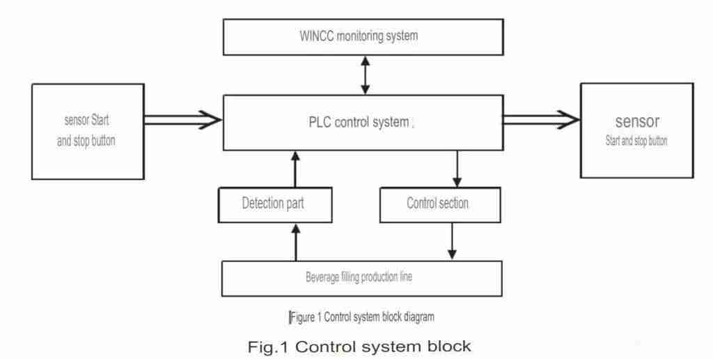
In 1996, Siemens WinCC industrial configuration software—a revolutionary window control center for the industrial market—was released to fulfill user demands in device drive, data acquisition, processing and analysis of information, process management, alarm handling, and reporting. Nowadays, it is widely applied with PLC technology across the automatic industry; this paper presents a case study in which WinCC has been combined with PLC to construct a beverage filling line production system.
The system's hardware comprises a Siemens S7-300 PLC and ancillary circuitry such as button control, sensor detection, and cylinder and motor drive. This PLC program regulates the cylinders' and motors' operation to finish the beverage bottle filling & capping process. WinCC applies TCP/IP technology to communicate with the said PLC while monitoring this entire procedure live via real-time observation. Figure 1 shows a diagrammatic representation of our designed control system configuration.
2.2 Basic structure of the control system
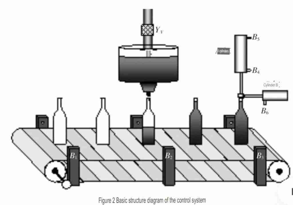
For the beverage filling line automation system, a conveyor powered by an electric motor is necessary, and three sensors have been integrated to achieve precise positioning while filling and capping. As demonstrated in Figure 2, this entire setup works together efficiently with precision, accuracy (etc.).
The capping station has two single-acting cylinders, A and B; each cylinder is accompanied by two in-place sensors for cylinder A and one for cylinder B. Furthermore, the PLC enables unparalleled automation that delivers a high level of accuracy when controlling conveyor motor starts/stops and filling or capping processes. Finally, every production line action can be monitored in real-time due to sensors paired with WinCC configuration software - allowing complete control over operations!
2.3 Control requirements of beverage filling production line
The specific control requirements of the control system are:
(1)Initiating the start button will set the system in motion and get the conveyor going. Whenever a bottle reaches its designated station, it triggers an automatic sensor which causes immediate stoppage of the conveyor belt.
(2)At the filling station, if a beverage bottle is present, it will be filled by a solenoid valve YV for three seconds with a visual warning signal.
(3)At the capping station, cylinder A performs the capping operation when a beverage bottle is present. Sensor B6 being activated indicates that the cap is locked in place, and after 1 second, cylinder A retracts. Additionally, sensor B4 signals for pressurized tightness, which causes Cylinder A to retreat after 1 second. Lastly, when sensor B5 operates, it informs that both cylinders have been properly retracted along with the conveyor rotating once more following one second elapsed .
(4)If the stop button is pressed, all handled processes will be stopped instantly (including conveyor motor stops, solenoid valve closing, and cylinder returning to its original position).
03.
Control system hardware design
3.1 Selection of PLC controller
The Siemens S7-300PLC is a force to be reckoned with-- featuring a flexible modular structure, easy integration of distributed settings, robust instruction set, extensive communication capabilities, and seamless programming software. The hardware architecture contains CPU, signal, and extended expansion modules that can meet any variation of automation control requirements. Due to its multiple integrated interfaces, maximizing the potential for both system control and subsequent communications between the configuration programming systems selection of CPU 315F-2PN/DP was necessary.
3.2 PLC system resource allocation
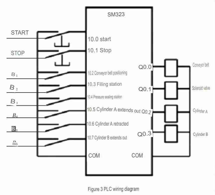
The PLC system resource allocation plays a crucial role in the hardware circuit design and provides essential information for software development. We chose Siemens' SM323 digital integration module for this project to serve our input and output control needs. We determined I/O address assignments - based on the object's control requirements – then recorded these outputs in Table 1 below (Figures shown).
| Table 1: PLC System Resource I/O Allocation | |||||
| Symbol | Component Address | Description | Symbol | Component Address | Description |
| S_Start | I0.0 | Start button, normally open | S1 | M10.0 | Initial step |
| S_Stop | I0.1 | Stop button, normally closed | S2 | M10.1 | Step 2 |
| B1 | I0.2 | Conveyor positioning sensor | S3 | M10.2 | Step 3 |
| B2 | I0.3 | Filling station detection sensor | S4 | M10.3 | Step 4 |
| B3 | I0.4 | Covering station detection sensor | S5 | M10.4 | Step 5 |
| B4 | I0.5 | Cylinder A extended position | S6 | M10.5 | Step 6 |
| B5 | I0.6 | Cylinder A retracted position | S7 | M10.6 | Step 7 |
| B6 | I0.7 | Cylinder B extended position | S8 | M10.7 | Step 8 |
| KM1 | Q4.0 | Control conveyor motor M1 | S9 | M11.0 | Step 9 |
| YV | Q4.1 | Solenoid valve | S10 | M11.1 | Step 10 |
| Y1 | Q4.2 | Control single-acting cylinder A | S11 | M11.2 | Step 11 |
| Y2 | Q4.3 | Control single-acting cylinder B | S12 | M11.3 | Step 12 |
3.3 PLC wiring diagram
Utilizing the I/O address designations and system controls, a PLC wiring diagram was fashioned to meet those specifications (Figure 3).
04.
PLC software program design
4.1 PLC program control flow chart
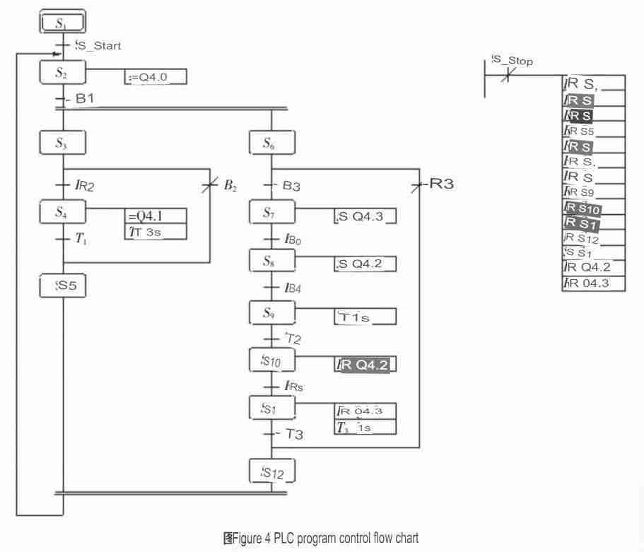
This program was built with the exacting control needs of the production system in mind. Actuators work according to a pre-defined flow and respond to multiple input signals, allowing for streamlined operations that improve efficiency. We created simultaneous filling and capping process capabilities to take it one step further so your production line can run at peak performance!
As the two stations have different operation times, a parallel branching process (view Figure 4) has been designed to produce maximum efficiency. The system comprises twelve states, each serving its own purpose: S2 facilitates transfer operations; S3-S5 regulates filling processes; and finally, S6-S12 manages capping methods .
4.2 PLC program
The WINCC monitoring program was orchestrated according to the control flow chart. Functions and actions were added to place it inside an FC subroutine, which is then called operating by OB1 - the main program.
| Network1: Initializer | Network9: Sensor B2 detects the presence of a bottle |
| A "S1" M20.0 | A "S3" M20.2 |
| #NAME? | A T3 |
| A L 0.0 | A (ON "B2" I0.3 |
| JNB 001 | ON M10.3 |
| L 80 | S "S5" M20.4 |
| T “PZ” MW22 Bottle X Axis | R "S3" M20.2 |
| 001: NOP 0 | Network10: B3 sensor detects no bottle |
| A L 0.0 | A "S6" M20.5 |
| JNB 002 | A (0 "B3" I0.4 |
| L 730 | 0 M10.4 |
| T “PGX” MW24 cap X axis | <= I) |
| 002: NOP 0 | S "S7" M20.6 |
| A L 0.0 | R "S6" M20.5 |
| JNB 003 | Network11: Cap seal B Cylinder extended into position B6 |
| L 419 | A "S7" M20.6 |
| T "PGY MW26 cap Y-axis | #NAME? |
| 003: NOP 0 | A L0.0 |
| A L 0.0 | A M100.0 |
| JNB 004 | FP M90.2 |
| L 742 | A(L “XB” MW30 B Cylinder X Axis |
| T “XB”” MW30 B cylinder X axis | L 698 |
| JNB 005 | >= I ) |
| Network2: start conveyor belt | JNB 009 |
| A "S1" M20.0 | L “XB” |
| A (0 "START" I0.0 start | L 1 |
| 0 M10.0) | #NAME? |
| "S2" M20.1 | T “XB” MW30 |
| R "S1" M20.0 | Network12: Cylinder A descends, puts B4 in place, seals the bottle cap |
| Network3: Conveyor belt movement | A "S8" M20.7 |
| A "S2" M20.1 | #NAME? |
| #NAME? | A L0.0 |
| A L0.0 | BLD 102 |
| BCD 102 | S "Y1" Q0.2 A cylinder |
| = "CS1" M66.6 Conveyor belt work | A M100.0 |
| A L 0.0 | FP M90.4 |
| A M 100.0 | A(L “YA” MW28 A cylinder Y axis |
| FP M 90.0 | L 337 |
| A(L “PZ” MW22 bottle X axis | <= I ) |
| L 180 | JNB 00b |
| <= I) | L “YA” MW28 |
| JNB 007 | L 1 |
| L “PZ” MW22 bottle X axis | #NAME? |
| L 1 | T “YA” MW28 |
| +I | Network13: press fit 5 s |
| T “PZ” MW22 Bottle X Axis | A "S8" |
| Network4: parallel branch entry | A(L “PGY” MW26 Cap Y Axis |
| A(L “PZ” MW22 bottle X axis | L 459 |
| L 180 | == I) |
| == I) | S “S9” |
| S "S3" | R “S8” |
| S “S6” | Network14: Cylinder restores, A cylinder rises to position B5 |
| R “S2” | A "S10" M21.1 |
| S “LB1” | #NAME? |
| S M60.0 Q1.0 | A L0.0 |
| Network5: | BLD 102 |
| A M60.0 | R "Y1" Q0.2 A cylinder |
| L S5T#2s | A L0.0 |
| SD T3 | BLD 103 |
| Network6: B2 sensor detects no bottle | R "LB4" Q0.4 |
| A "S3" M20.2 | A L0.0 |
| A (0 "B2" I0.3 | FP M90.6 |
| 0 M10.3 | A (L “YA” MW28 A cylinder Y axis |
| <= I) | L 298 |
| S "S4" M20.3 | > I) |
| R "S3" M20.2 | JNB 00d |
| Network7: Beverage Filling | Network15: Cylinder restores, B cylinder retracts to position B6 |
| A "S4" M20.3 | A "S11" M21.2 |
| #NAME? | #NAME? |
| A L0.0 | A L0.0 |
| BLD 102 | BLD 102 |
| YV | R “Y2” Q0.3 B Cylinder |
| A L0.0 | A L0.0 |
| A M100.0 | BLD 103 |
| FP M90.1 | R "LB4" Q0.4 |
| A (L "G1" | A L0.0 |
| L 100 | FP M90.7 |
| JNB 008 | A(L “XB” MW30 B Cylinder X Axis |
| L "G1" | L 298 |
| L 1 | > I) |
| + I) | JNB 00d |
| T "G1" | Network16: Parallel branch exit |
| Network8: | A "S5" M20.4 |
| A "S4" M20.3 | A "S12" M21.3 |
| A (L "G1" MW32 | S "S13" M21.4 |
| L 100 | R “S12” |
| == I) | R “S5” |
| S "S5" M20.4 | |
| R "S4" M20.3 |
05.
Beverage filling production line
A division of labor is established between the software and upper/lower computers to design the system. The WinCC configuration software will create an efficient human-machine interface while real-time data display and monitoring occur onsite. Additionally, PLC can control channel selection with production line supervision .
5.1 Configuration variables
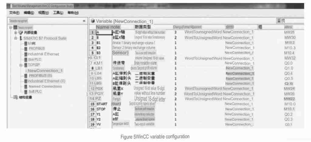
The variable system of the configuration software is an essential element, as it enables WinCC to reflect production conditions at an industrial site in real time. Operators can monitor process data and send commands directly from their computer terminal through these variables instantly transmitted to the relevant area onsite. For more information regarding this feature, please refer to Figure 5 in our System Variables Table!
5.2 Design of monitoring interface
The WinCC configuration software easily configures the supervisory interface to achieve various looks and purposes. Its open extensions and an expansive library make it effortless to create interfaces that meet whatever needs you may have regarding automating production line control and monitoring processes.
5.2.1 Main interface
The main interface boasts a range of project-related data, including the project's name, design team members, the timespan for completion, and an assortment of navigation buttons to help switch between windows.
5.2.2 Production line monitoring interface
Displaying the system start and stop buttons, the set and current level values, and line details in an easy-to-view format—the user-friendly line monitoring screen effortlessly allows you to adjust filling volume or cap sealing force without needing extra steps. Quickly switch between screens for a swift transition from one task to another!
5.2.3 Real-time data collection - trend and alarm interface
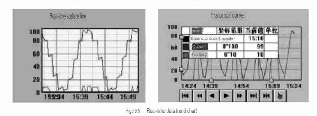
As illustrated in Figure 6, the system consistently shows the process data of beverage filling operations as a curve. An alarm will be triggered if filling levels surpass an established upper limit.
5.2.4 Simulation debugging
To get up and running with the STEP7-software, download the compiled program to your PLC and switch on emulation debugging. Then open Micro WinCC software to establish a connection between it and your PLC - once you've launched the main monitor screen, executing the program will cause complete commissioning of your beverage filling line!
06.
Conclusion
In conclusion, this paper introduces a beverage filling production system that is automated using the Siemens S7-300 PLC core controller and monitored through WinCC configuration software. The proposed control system proves to be highly automated, efficient, and stable, with an intuitive human-machine interface that enables improved production efficiency and reliable management. The simulation results demonstrated in this paper highlight the effectiveness and reliability of the proposed system.
Furthermore, it is worth mentioning that the concepts and methodologies presented in this paper can also be applied to other beverage production machinery such as Carbonated Soft Drink (CSD) filling machines, bottled water filling machines, fruit juice filling machines, bottle blow molding machines, and water treatment systems.
While the proposed system shows promising results, we understand that there are still opportunities to further enhance the intelligence of the beverage filling production system. Future research will be focused on optimizing and extending the capabilities of the proposed system to ensure even greater efficiency and reliability in the rapidly evolving beverage production industry.
By consulting iBottling, beverage manufacturers can gain access to cutting-edge technology and streamlined processes for their beverage production line control needs. Our team of industrial automation experts provides high-quality customized solutions that guarantee optimal output and efficiency for your business. Reach out today to see how we can help you with your project!
Reference
- https://support.industry.siemens.com/cs/document/109483779/line-integration-concept-for-the-food-beverage-industry-(overview)?dti=0&lc=en-af
- https://www.scientific.net/AMM.563.366
- https://www.researchgate.net/publication/333922724_Design_of_Control_System_for_Warehouse_based_on_PLC
- https://www.foodprocessing.com.au/content/processing/white-paper/integration-optimise-your-production-and-packaging-lines-276517030/download
- https://www.grafiati.com/en/literature-selections/siemens-control-system/journal/
- https://maxwellsci.com/jp/mspabstract.php?doi=ajfst.7.1259
- https://www.2s-automation.cz/en/realizations/
- https://www.journaleras.com/index.php/jeras/article/download/13/13
- https://uir.unisa.ac.za/bitstream/handle/10500/25772/dissertation_kiangala_ks.pdf?sequence=1&isAllowed=y
- https://repository.neelain.edu.sd:8080/jspui/bitstream/123456789/16531/1/Automatic Bottle Filling System Using PLC%2C SCADA and Variable Frequency Drive.pdf
- https://www.ats-global.com/knowledge/automation-it/
- https://www.ripublication.com/irph/ijert19/ijertv12n6_03.pdf
- https://patents.google.com/patent/CN101292683A/en
- https://eg.linkedin.com/in/mahmoud-gad-631b6190
- https://ijciras.com/PublishedPaper/IJCIRAS1349.pdf
- https://www.festo.com/net/en-ae_ae/SupportPortal/Files/425964/Teciam - Release 3.0 EN.pdf
- https://3x3elitesardinia.it/automatic-bottle-filling-machine-using-arduino.html